|
|
|||||||||||||||||||||||||||||||||||||||||||||||||||||||||||||||||||||||||||||||||||||||||||
|
Chapter 9 |
|||||||||||||||||||||||||||||||||||||||||||||||||||||||||||||||||||||||||||||||||||||||||||
|
Moulds and Mould Design |
|||||||||||||||||||||||||||||||||||||||||||||||||||||||||||||||||||||||||||||||||||||||||||
|
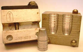
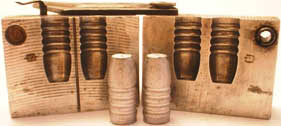
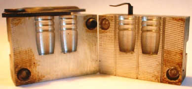
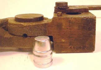
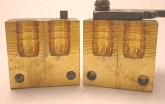
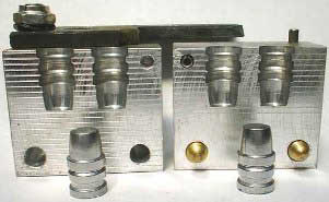
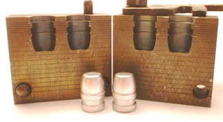
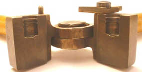
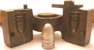
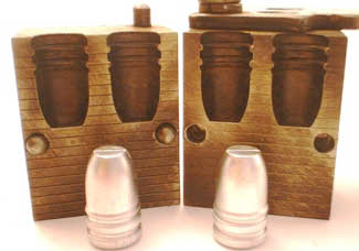
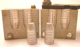
What goes into making a bullet mould? What should you consider if you want to make your own design? What are the variables involved and what decisions will you have to make in the process? Mould making materials. Traditionally, bullet moulds have been made out of iron or brass, and more recently aluminum has become popular as a result of its availability, ease of machining and high thermal conductivity. But do moulds have to be made from such stuff? Are there better materials out there? What else has been tried?
Iron isn't all that hard, so it machines fairly easily, but the iron carbide inclusions in cast or forged iron make it very abrasive and hard on the cutting edges of the cherries (this is why RCBS uses tungsten carbide cherries to cut their moulds). Brass cuts very smoothly and is very gentle on cherries. Aluminum also machines easily, but the cut faces are not as smooth as those on brass. Aluminum alloys are also more prone to warpage than brass (although this can be dealt with through appropriate stress relieving).
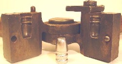
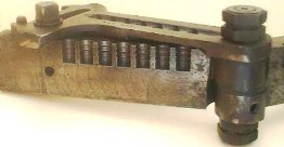
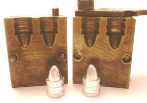
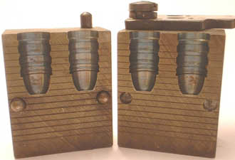
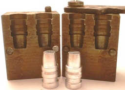
Belding & Mull cut their mould blocks out of nickel. Meehanite (a cast iron alloy) has also been a popular mould making material, as has bronze. There are also a few experimental modern bullet moulds made from fired ceramic, with hardened steel alignment pins. There are a number of advantages to using ceramics to make mould blocks (excellent thermal stability, very smooth surfaces, ease of manufacture, lack of warpage, etc.), just don't drop it! In the Field Museum of Natural History in Chicago there is an Inuit bullet mould that was hand-carved out of a single, split Walrus tusk. I stood staring at that display for quite some time, imagining the many long, cold, lonely nights spent carefully splitting, facing, hinging, and shaping that ivory in some remote igloo until the round balls that fell from it were just right for whatever musket that hardy soul used to feed himself with. I have also seen similar handmade Indian bullet moulds made from bone (buffalo, as I recall), and even bullet moulds in which the cavity was hollowed out from well-worn river-bottom stones (a stone mould with no handles has got to get HOT!). Number of cavities. Historically bullet moulds were single cavity. After WWI, 2x and 4x moulds gradually started to appear, and after WWII became quite popular with individual casters. "Gang moulds" (6 or more cavities, also called "Arsenal moulds" or "Armory moulds") were traditionally used for the high volume, bulk casting needed by law enforcement groups and shooting clubs. These mammoth moulds take a long time to heat up and are of limited utility to a hobby caster who wants to cast only a few hundred bullets at a time (this is less of an issue with aluminum gang moulds due to their ability to heat up quickly). Alignment pins. Early bullet moulds had no alignment pins, relying instead on the massive hinge pin to keep the mould blocks aligned. Later fixed handle moulds from
Ideal incorporated alignment pins. Detachable mould blocks must have alignment pins as there is too much free play and too much variability in mass produced blocks; without this alignment mechanism to make sure the mould faces line up perfectly, your bullets would come out lop-sided. Venting. Early Ideal moulds (i.e. fixed handle, single cavity) had no vent lines cut in the mould faces by the factory. The transition was made to interchangeable mould handles/blocks, but the mould faces remained unvented. In 1949 Lyman introduced 2-cavity mould blocks, and virtually
all of the double cavity moulds I have seen have been vented, but there are a few exceptions (e.g. Himmelwright 2x), suggesting that factory cut vent lines came about after this date. Reviewing the Ideal Handbooks, moulds are not shown as being vented until Handbook number 43 (1964), but no mention is made of this in the text, or when the change was made. The purpose of these vent lines is to allow air to escape as the cavity is filled, allowing the mould to fill out properly and prevent voids in the finished bullet. Virtually all bullet moulds are vented in some way today.
Aspects of cast bullet design Every cast bullet design has the same set of variables that can be tweaked according to the desires of the designer. There is very little "new under the sun" it's really more of a question of refining what is already out there, and playing some subtly mix-n-match games to combine all of the desired features in one bullet (heck, even this sentiment is recycled -- Elmer Keith said the same thing about his Keith SWC's back when he started designing those back in 1928!). These variables include the bullet base design (PB, BB, GC, etc.), the amount of contact bearing surface employed, the shape, number and location of lube grooves, the location and configuration of the crimp groove, the diameter and thickness of the forward driving band, the length of the bullet's nose, the shape of the ogive and the diameter of the meplat. Sounds like a lot of fun, right? Bearing surface. Traditionally, handgun bullets have had about half of their length used as bearing surface (rifle bullets generally use more). More recently, there has been a move towards heavier handgun bullets for deeper penetration, and this in turn has lead to longer handgun bullets with more bearing surface. Bearing surface is a good thing in that it makes sure that the bullet stays concentrically aligned within the throat and transitions smoothly from the throat to the forcing cone to become engraved in a symmetric and concentric fashion. The SSK designs are excellent examples of handgun bullets that take advantage of lots of bearing surface (60+%) and deliver excellent accuracy. The bottom line is more bearing surface makes for an accurate bullet since it helps to keep the bullet well-centered during engraving and as it travels down the bore (the Loverin rifle designs are another excellent example of how lots of bearing surface contributes to an accurate design).
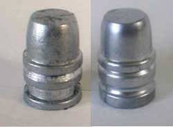
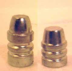
Lube grooves. All cast bullets need to be lubricated (see lube chapter), and this lube has to go somewhere. Way back when, 90 degree right-angled grooves were cut into mould designs for this purpose, and if you've ever cast with these moulds you know what a pain they can to deal with! As bullet metal shrinks, it shrinks towards the geometric center of the bullet, meaning that the driving bands end up "pinching" the mould at the 90 degree grooves, so the bullet holds fast and does not release from the mould readily. Two methods are commonly used to get around this problem: one is to cut these grooves with a slight bevel to them, and the second is to cut round lube grooves. Both approaches work just fine to provide "pinch-relief", but the rounded lube grooves generally hold less lube than a beveled flat-bottomed lube groove (what Elmer Keith liked to call a "square-cut" lube groove). Usually, this is of little concern since the rounded lube grooves are smaller and more of them can be used to decorate the bullet's bearing surface, resulting in the same overall quantity of lube. The important issue is how much lube is carried in the lube groove(s), and that they be capable of pumping the lube to the bullet/bore interface (see lube chapter).
Crimp groove. Originally, handgun bullets had no provision for crimping, they were simply seated to a depth that allowed the case to be roll-crimped on the ogive. Heel bullets were simply crimped on the heel shank. A very few of the early (pre-1900) rifle bullets had crimp grooves, but most did not. It's important to remember that these plain-based bullets were designed for black powder, or light charges of smokeless powder ("gallery loads"). The recoil impulse of the gallery loads was light enough that bullets didn't move around in the case, and when these rifle bullets were seated on top of a case full of black powder, the compressed powder charge prevented them from being forced into the case when "waiting in line" in a tubular magazine. Thus, the only need for a crimp was to keep a revolver bullet from inching forward under recoil, and a roll-crimp over the ogive was usually sufficient for black powder level ballistics. Smokeless powder would change all this. Suddenly handgun cartridges cases had empty space in them, and velocities were no longer limited to about 900 fps. Beveled grooves dedicated to crimping had been introduced in rifle bullets with designs like the Ideal #3083 (for the Marlin .30-30), and were a natural next step in the evolution of handgun bullet design. As near as I can tell, the first handgun bullet to contain a beveled crimping groove was the Ideal 313226 (the 98 grain round-nose for the .32 S&W Long). This system worked so well that others soon followed (e.g. 313249, 358311, and 429251). Elmer Keith identified the 358311 as his inspiration and identified the beveled crimp groove as one of the more important design features of his SWC designs (his .38-44 Heavy Duty loads and heavy .44 Special loads generated significant recoil and required a strong crimp to keep the bullet from inching forward). Beveled crimp grooves have been standard fare on all revolver bullets ever since (although the angle, depth and length can vary considerably from one design to the next).
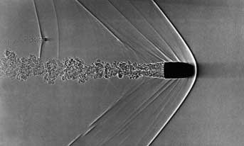
Ogive/meplat. The ogive and meplat play a central role in determining how stably the bullet will fly and how efficiently it works upon impact. But these features also play a role in the internal ballistics of the load as well. How long is nose of the bullet? In other words, how much of the bullet is seated outside of the case? What is the resulting powder capacity? This will have a direct impact on how fast that bullet can be driven and still stay within sensible pressure limits. The role of the meplat in crushing tissue and leaving a permanent crush cavity is well established; the larger the meplat, the larger the hole it leaves in its wake. This is why hunting bullets (e.g. Keith SWC's, SSK FP's or LBT WFN's) all have flat noses that are greater than half the bullet's diameter. Flat-nosed bullets are simply more effective and more humane killers. What is not commonly discussed is the role that ogive/meplat play in the aerodynamic/hydrodynamic stability of the bullet. The dynamics of how a bullet flies through the air, as well as how it flies through meat, is an important consideration when choosing a bullet to hunt with. Does a given design lead to deep, straight wound channels, or does it tend to tumble and veer off in unpredictable directions? Aerodynamics. The meplat and ogive play a significant role in determining the aerodynamic stability (and hence accurate flight) of a given bullet design. When a bullet is traveling faster than the speed of sound, there is a high pressure bow wave that emanates from just in front of the meplat, and trails back behind the bullet. The bullet is basically acting as a piston, compressing the air in front of this cone, with somewhat rarified air (partial vacuum) behind the cone, along the bullet's body. (As an interesting aside, high power rifle competitors will commonly "de-tune" their spotting scopes to focus about halfway down to the target in order to be able to read mirage and dope the wind. This also allows them to "see" the bullet in flight and read the trajectory and wind drift in flight and see where the bullet is being blown of course. This conical pressure wave, and the change in the air's refractive index from the high/low pressure regimes, is what is being observed by these shooters.) Back to the story -- tests have shown that the ballistic coefficient is more heavily influenced by the ogive, than it is by the meplat. The reason for this is quite simple, the drag experienced by a bullet in supersonic flight is due to the size and shape of this conical bow wave. The surface area of the meplat is actually quite small relative to the surface area of this entire cone, and so the amount of drag actually due to the flat nose of a bullet (again, in supersonic flight) is fairly small. However the size and shape of this conical bow-wave are directly dependant on how easily it can "wrap itself around" the shape of the bullet, and with a shapely ogive the cone angle is smaller, and therefore the size of the conical bow-wave is smaller and the bullet experiences less drag going downrange. Likewise, when viewed from the side, the cross-sectional area of the cone is smaller, and since it is the "sail area" of this bow wave that dictates how susceptible the bullet is to wind drift, the more shapely bullet gets blown around in the wind less because it has a smaller sail. The combination of these two factors, less drag (hence greater retained velocity, and shorter time of flight) and smaller bow-wave cross-sectional area (a smaller sail for the wind to blow it off course with) are the reasons why boat-tailed bullets drift less in the wind than do flat-base bullets.
The forward portion of the ogive is thus a very important part of equation, as it plays a heavy role in shaping the bow-wave and determining how well the nose of the bullet "fits" inside of it. A sharp edge at the meplat/ogive juncture (such as one would get from a truncated cone, e.g. the Gordon Boser or Lee SWC designs) leads to a situation where the only stabilizing influence this bow wave can have on the bullet is through this perimeter around the edge of the meplat. By placing curvature at this juncture by making the ogive radiused, the bow-wave is able to wrap around the nose of the bullet, leading to a contact surface instead of just a contact edge. Why is this important? Well, this bow-wave acts as a dampening agent to damp out any yaw that the bullet might experience. Ever hear of a bullet "going to sleep"? That's just a reflection of how long it takes for any yaw inherent to the launching of a given bullet to be damped out by this mechanism (in combination with a couple of other factors). The efficiency of this damping mechanism is basically proportional to the amount of surface area that the pressure wave can act upon. In the case of the contact edge, there's relatively little that the bow wave can do to stabilize this yaw, but with a radiused contact surface this damping mechanism becomes much more efficient. Hydrodynamics. Clearly, a large flat meplat results in greater ability to crush tissue upon impact, however, it is also well established that extremely large blunt meplats (e.g. wadcutters) are aerodynamically unstable and prone to tumbling upon perturbation. It is important to recognize that while the meplat determines the shape and nature of the wound channel when a bullet plows through meat, the ogive determines how stably the bullet "flies through meat". All of the arguments given above in the discussion of aerodynamics also apply here. It is interesting to note that J.D. Jones once noted that all of the cast bullets he recovered from big game animals all looked pretty much the same, and he used that shape as part of his inspiration for his SSK designs. He figured that if that's the equilibrium shape that a bullet achieved after punching through a critter, then starting it off in that shape should provide a reasonably smooth "flight" through more meat. Optimum meplat diameter. OK, so we know that a big meplat is a good killer, but that too much meplat makes a bullet unstable in flight. How much meplat is too much meplat? Let's look at a few successful designs for some guidance here. Elmer Keith started off with a meplat diameter of 65% by borrowing Heath's ogive and meplat for the Ideal 429336. Keith then used 75% on his 452423, then settled on 68-70% for his 454424, 358429 and H&G #258 (.41 Magnum). J.D. Jones has used 70-75% meplats for his SSK designs. The LBT WFN is profiled by making the meplat .090" less than bullet diameter, so the relative diameter is not constant (75% for .358", 78% for .410", 79% for .429" and 80% for .452. The Keith SWCs and the SSK FPs are some of the most accurate handgun cast bullets that I've ever shot, and while the WFN bullets are superb hunting bullets, and are capable of fine accuracy, there are reports that they can be finicky about delivering their best accuracy, and can tumble upon impact (just like a wadcutter). In contrast, the big-bore LFN bullets are generally regarded as being inherently more accurate than their WFN brethren, with far better long-range stability than the WFN designs, and the LFN's have a reputation for penetrating nice and straight and deep. The LFN meplat is approximately .140" smaller than bullet diameter, or 67% for .429" and 69% for .452". Ignoring the contribution of the forward driving band for a moment, a purely empirical correlation suggests that the optimum compromise between stable aerodynamic flight and maximum tissue crushing capability occurs with a meplat of about 70-73% of bullet diameter. The concepts outlined above for the ogive/meplat apply for supersonic flight, subsonic flight is a little different matter that we'll tackle shortly in our discussion of the driving bands and lube grooves. When the bullet is flying at subsonic velocities, then all of the arguments that you hear about shapely bullets really do apply, simply because in subsonic flight all of the features of the bullet's profile are in intimate contact with the slipstream, particularly below a Mach number of 0.85, or about 900 fps, where the slipstream is particularly conformal (at higher Mach numbers there are local pressure ridges along the projectile body, these grow into the bow wave and other pressure features at Mach 1). In subsonic flight, the primary source of drag is now that big, flat meplat since the conical bow-wave no longer exists. Again, in terms of influencing the aerodynamics of a handgunner's cast bullet, the ogive exerts the major influence in supersonic flight, while the meplat dominates in subsonic flight. For competition (silhouette, bullseye, PPC, etc.) meplat diameter is immaterial, and the ogive is all important for optimum bullet performance. This is why cast bullets designed for silhouette competition tend to have smaller meplats and more curvaceous ogives. Forward driving band. Elmer Keith felt very strongly about a full-sized forward driving band, both in terms of bullet diameter (to insure that the bullet was properly centered upon engraving) and in terms of width (to provide enough bullet metal for the lands to grip firmly and prevent slippage during engraving). The forward driving band probably doesn't do anything in terms of cutting the wound channel through yon deer since these forward driving bands have the tendency to get "wiped off" while traversing flesh, but they DO play a significant role in the flight behavior of cast bullets. A full diameter forward driving band is very important to keep the bullet properly aligned, however if this is much longer than about .100" then it can cause problems with chambering the round unless the bullet is seated in a perfectly concentric fashion (a rarity) and is smaller in diameter than the throat (which is not always a good thing). Therefore, by keeping the forward driving band to .100" or so, it is readily accommodated by the taper of the leade from the chamber into the throat, and will chamber easily. How tall should the forward driving band should be? In other words, when viewed from the side, how far should the driving band stand up over the base of the ogive? A shorter driving band means that the stresses associated with engraving are able to be distributed to the monolithic portion of the bullet, but if the base of the ogive is too small in diameter then this leaves the forward driving band to absorb the engraving forces all by itself, which can lead to slippage if the alloy isn't up to the task. By making this forward driving band as short as possible (i.e. by making the base of the ogive as large as possible) the forward driving band is provided the maximum amount of support. At this point, the bullet designer has a bore riding nose, which maintains the desirable turbulence of the driving band edge (vide infra), provides maximum bearing surface and provides positive engagement during engraving. Aerodynamics. A very important consideration to long range high-power rifle shooters (e.g. 1000 yard) is the need to keep the bullet supersonic through the target. This is because as the bullet slows back down through the sound barrier and the supersonic bow-wave collapses, these long, sleek BTHP match bullets become destabilized and eventually start to tumble. Accurate flight is a thing of the past at that point. Therefore it is critical to these competitors that the bullet stay supersonic at least as far as the target distance. Why was this not an issue for the 1000 yard shooters of the 1870s shooting the Trapdoor Springfield? Those loads started out supersonic, and transitioned to sub-sonic about halfway to the target and yet those bullets continued to fly in a stable and predictable manner for hundreds of yards. The BPCR silhouette shooters of today are able to pull off the same feat, but their compatriots shooting the bolt-guns and the BTHP jacketed match bullets suffer keyholing, tumbling and non-visible misses once their projectiles transition sub-sonic. Why? What do the BPCR shooters have working in their favor that the hi-power riflemen do not? The same questions apply to IHMSA shooters armed with .44 Magnum revolvers. There are many facets to the answer, but probably the most important is understanding HOW the bow-wave collapses during this transition, and recognizing the influence that certain cast bullet features have on that collapse. The key is found in the nature of the airflow in the boundary layer, specifically whether this flow is laminar or turbulent. Allow me the indulgence of a historical caveat to introduce this concept. In the early days of aerial bomb design, engineers added fins to make the bombs fall "nose forward" and therefore in a predictable trajectory, giving them the best chance of hitting their target (kind of like the fletching on an arrow). As bombs got bigger and bigger, so did the fins. With really large bombs, it was found that even over-sized fins were just barely able to stabilize the flight attitude of the bomb, and that relatively minor perturbations would lead to loss of aerodynamic stability. Wind tunnel tests revealed that the large volume of air displaced by these huge bombs, coupled with a more or less smooth, laminar airflow, resulted in the slipstream basically "missing" much of the surface area of the fins (as well as generating destabilizing "eddies" back around the fins). A laminar airflow basically makes the bomb much larger in diameter, so most of the air basically has to go around what behaves like a much larger object. It was found that adding three small, radial ridges around the midsection of the bomb cured this problem. The thinking here is that the turbulence induced by these tiny ridges collapsed the large laminar airflow, and allowed a more conformal airflow that now flowed smoothly across the control surfaces of the fins. The take-home lesson here is that small amounts of controlled turbulence at the surface of a body leads to smoother airflow and more stable aerodynamic flight, just like the seams on a baseball allow for a predictable curve ball to be thrown by creating a small amount of turbulence at the surface which leads to smoother air-flow (somewhat counter-intuitively, a smooth ball would break even more and be difficult for the pitcher to control, see The Physics of Baseball by Robert K. Adair, Professor of Physics, Yale University). In supersonic flight, the bow wave is typically a little ways in front of the nose of the bullet (roughly 1/8" to 1/4"). It is parabolic in shape. How the forward portion of the bullet's ogive "fits" inside this parabola is important to determine long-range stability. As the bow-wave collapses, the parabola starts to flatten out, and the nose of the projectile starts to penetrate the forward point of the bow wave, which then slips back over the projectile. The parabola continues to flatten due to the reduced pressure differential between the compressed air in front of the bow-wave and the rarified air behind it. This collapse/penetration leads to a cascade of events: first as the nose of the bullet penetrates and the pressure-wave slips farther back on the bullet. Sharp shoulders, or surface features, create secondary shock waves, due to the better ability of these surfaces to compress the air they encounter. Shadowgraph photography of supersonic cast bullets clearly shows shock waves emanating from the lube grooves and other structural features of the bullet's surface. As the bow wave slides back over these structural features, these shock waves serve to dissipate the energy of the bow wave in small pieces as the bullet slows back down through the sound barrier. The forward driving band is the first such structural feature that the dying bow wave encounters, and as such it has the biggest chunk of energy to dissipate since it's taking on the full brunt of the bow wave. The shock waves emanating from the crimp groove and lube groove(s) continue this break-up process as the fractured bow wave slides farther back, creating a turbulent boundary layer and dissipating the bow wave's energy in benign fashion. Bullets lacking the perpendicular face of the Keith SWC forward driving band can get a similar effect from lube grooves, although these are less efficient and more are required (a la the Loverin bullets). It's important to recognize that this bow wave is in fact what the air "sees" in terms of the wind resistance and drag that the projectile experiences, so by slowing the departure of the pressure wave it serves to maintain drag on the rear portion of the bullet, helping to keep the bullet oriented nose forward. The boundary layer turbulence resulting from the forward driving band and lube grooves disrupts this pressure wave as it collapses towards the bullet base. As a result, the pressure wave is broken up over a period of time and dispersed in such a way that the airflow becomes turbulent conformal in a way conducive to stable flight (basically the energy is dissipated in small "packets" as turbulence/heat). For the smooth-surfaced jacketed BTHP, this penetration/collapse happens in much the same way, but the relative lack of surface features to break up the pressure wave, means that this wave collapses quite quickly, as a shock wave, and with a clap (quite literally a "sonic boom"). At the extended ranges that a high-powered rifle bullet is slowing through the sound barrier, it is traveling with a significant angle of incidence, which in turn means that this pressure wave moves backwards at different rates over the top of the bullet than it does over the bottom of the bullet. Therefore, these pressure waves leave the bullet's base at different times, resulting in an asymmetric force on the bullet's base as the shock wave ("sonic boom") collapses. This sonic "kick in the backside" can induce significant yaw (or amplify any yaw that is already present), and for a bullet spinning at well in excess of 100,000 rpm, that's all it takes to start tumbling. The important take-home message here is that this effect is transmitted through the bullet's base -- whether the bump comes a single, massive, axle-breaking pothole, or a series of several smaller "washboard" bumps. Which one is easier to steer through? It is interesting to realize that some of the very things that make a cast bullet ballistically inefficient overall, also make it aerodynamically MORE stable when slowing back through the sound barrier. Specialized designs Elmer Keith designed his SWC's to be general, all-purpose bullets so a shooter could buy one mould and use that one bullet for just about any task that he was likely to encounter. When we distill down all of the discussion above, it is readily apparent why these bullets work as well as they do. However, many cast bullet designs have been put together around very specialized features, for highly specific applications (especially in recent years). After all, bullet casting is affordable enough that a shooter can afford to have one mould specifically for one flavor of competition, another mould for a different form of competition, a third for hunting small game and yet another for hunting big game. Sometimes these specialized features amount to little more than passing fads, or reflections of shooting disciplines that came and went, but some of these specialized cast bullet designs stake a claim within the shooting community and take up permanent residence.
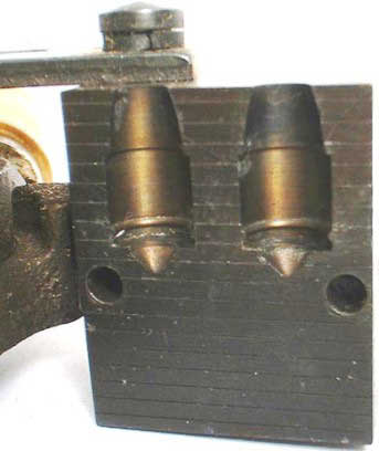
Nose pour. By placing the sprue on the bullet's nose, the bullet's base can be made more rigorously square to the bullet body since it now being turned as a part of the cavity, and hence on the same axis. Since the bullet's base is it's "steering end" (i.e. the last part of the bullet to leave the muzzle, and the part most heavily influenced by the blast of gas escaping from behind as it leaves) having this feature perfectly square is a critical component to obtaining top accuracy. As a result, nose-pour moulds are popular with long-range rifle shooters and Schuetzen competition. Most commercially available base-pour moulds are pretty good in this regard, but if a mould has got a loose or bent sprue plate, or if the top edge of the cavity has gotten dinged, or the top face of the mould has been damaged, then the quality of bullets coming from that mould are suspect. The quality of bullets emerging from a nose-pour mould will not be seriously compromised by these injuries. Dr. Franklin Mann's book (1909) The Bullet's Flight from Powder to Target stressed the importance of symmetrical and well-formed bullet bases. Asymmetries, distortions, fins, defects will destroy the accuracy of a cast bullet, and Dr. Mann's detailed, systematic experiments revealed exactly how these deformations impacted accurate flight. By making a nose pour bullet the base will be perfect and will not be susceptible to asymmetries resulting from a bent or loose sprue plate or trapped air pockets, inclusions or voids. Note that by having the base at the bottom of the mould, since lead is much more dense than air or particulate impurities, that these detrimental defects are forced away from the all-important base simply by the force of gravity (a base pour mould can concentrate these defects at the bullet's base with dirty alloy or sloppy casting conditions).
Harvey Prot-X-Bore. In the mid-1950s, Jim Harvey designed a series of moulds that were made to accommodate zinc washers so that bullet metal was cast through the hole in the center of the washer, thus permanently affixing the bullet to the washer. (Interestingly, these are seen in both base-pour and nose-pour configuration. Most of the Harvey moulds I've seen have been the nose-pour configuration. In base-pour format the molten alloy has to be poured through a cold zinc washer and I suspect wrinkled bullets were the norm with this style of mould. With a nose-pour mould the only lead that has to go through the washer is the rivet that holds it in place). The idea behind this design was to allow the use of pure lead (or very soft alloys) so that bullet expansion could be maximized at typical handgun velocities, and also to eliminate gas cutting and the need to size-lubricate the bullet after casting. The zinc washer was touted as being a bore scraper and removing lead fouling, as well as depositing a zinc layer on the bore, protecting it from oxidation and leading. These Harvey bullets were promoted as not needing to be lubricated, but that was pretty much limited to standard velocity loads and leading could get to be pretty severe at higher pressures/velocities.
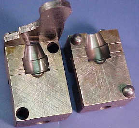
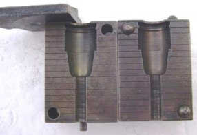
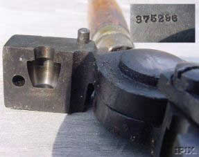
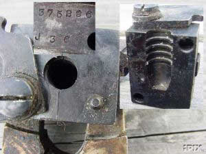
Two part bullets. The idea of controlled expansion has been with us for a long time. The 1915 Marlin-Ideal catalog lists four 2-part bullet moulds -- the 308291 (165 grain GC-RN for the .30-30, .303 Savage and .30 Remington), the 319295 (a 175 grain GC-FP for the .32-40), the 321297 (a 182 grain GC-FP for the .32 Winchester Special), and the 375296 (a 253 grain GC-FP for the .38-55). Note that these cherry numbers are all in the 290's, which would suggest that their introduction was right around 1902. Note also that these moulds all represent medium caliber arms. Apparently the thinking was that producing shootable 2-part bullets in smaller calibers would be too difficult, and that the larger bore weapons already made big enough holes. Anyway, the idea here was to cast the front quarter or so of the bullet with either pure lead or a very soft alloy, and then to place this soft "mushroom" (it had a "stem" to help bond the two halves) in the regular mould cavity and pour the back half with a harder alloy. The design concept is not unlike the Partition and H-mantle bullet designs (just a little bit older). These moulds are occasionally encountered on the used mould market today, but commonly command premium prices. Mountain Moulds of Pocatello, Idaho offers 2-piece moulds for a wide variety of mould designs (http://www.mountainmolds.com/). A few years ago, Ross Seyfried wrote up a similar project (Handloader, April-May 2003) which could be pulled off with standard moulds and likely produce higher quality projectiles. The drawbacks of the 2-part bullet process as originally promoted by Ideal (outlined above) is that the bullet results from 2 separate casting operations; the nose is done first and then the base is poured later. This process schematic creates 2 significant roadblocks for the efficient production of high quality projectiles. First, it requires that the nose portion be handled and inserted into the hot mould (a good way to burn fingers! using tweezers prevents burned fingers, but significantly slows production); and second, the nose portion is cold when the base is being poured over it (which can cause voids and defects). Ross formulated a very clever strategy to get around all of these problems, and do it with standard moulds. His process involves the use of 2 separate lead pots, one filled with soft alloy (say 30-to-1), the other filled with hard (like wheelweight or 6-2 alloy). A special fixed-capacity ladle is made for the soft nose portion (I used a fired 9mm casing with a coat-hangar wire handle wrapped around it), this ladle is filled to the brim with soft alloy and poured into a hot mould. As soon as this pour is completed, the ladle is set aside and the mould is transferred to the bottom pour pot containing the hard alloy and the cavity topped off normally. This method obviates the need to handle the soft nose portion and the hard base is poured when the nose is still hot, so an effective soldering is achieved between the two portions. Yes, this process is somewhat slower than just plain casting, but there is no need to do this for garden variety plinking bullets, only those bullets that are going to be used for hunting. More recently (around 1982), Lyman revived this idea with a series of 2-part revolver bullet mould designs that they called "composite bullets" (mould numbers 358624, 429625 and 452626) that were designed by Kenneth Ramage. These were variations on the SWC theme in which the soft nose was glued into a conical cup in the harder base. These moulds apparently didn't sell very well and were dropped from the Lyman line later in the 1980s.
Multiple projectile loads. Shooters have been interested in multiple projectile loads for centuries. Whether grapeshot from medieval cannon, or buckshot from a farm-boy's shotgun, the ability to land multiple projectiles on a target has always had both strategic importance, as well as functional appeal. The modern revolver shooter is no different. One of the early attempts to bring multiple projectile loads were the Remington .38 Special loads that contained a couple of buckshot pellets. Accuracy was marginal, but they were designed for close-range self-defense. Around 1980, Dean Grennell got H&G to make him a mould that cast a short, flat WC that contained a single grease groove and could be stacked inside a .38 Special or .357 Magnum case to allow the home caster to create similar home-brewed self-defense loads.
JDJ. In the 1980s, J.D. Jones of SSK Industries brought out a new line of cast bullets that were specifically designed for the handgun hunter who wanted to take on the heaviest big game with a revolver. These bullets were typified by being heavy for caliber (e.g. 280 grains for .41, 320 grains for .44, and 350 grains for .45), having lots of bearing surface, multiple lube grooves and a healthy meplat (typically 70-75% of bullet diameter). These bullets were the first "heavier than normal" bullets designed for revolvers, and are designed for deep penetration, with a truncated cone design. Their meplats are typically a little larger than those found on Keith SWC's. The 320 grain .44 Magnum bullet has been used to kill pretty much everything, up to and including elephant. I have SSK moulds in a number of different weights in .357, .41, .44, .45 and .475 diameters and they have all consistently delivered excellent accuracy. These moulds were available in PB, GC and BB form. Originally, these moulds were commissioned by SSK and manufactured by NEI (these moulds are stamped SSK), and later the rights to sell these moulds was sold to Peter Pi at Cor-Bon. The SSK designs are still cataloged by NEI, now located in El Paso, Texas.
Silhouette. IHMSA was a major form of competition in the 1970s and 1980s. To be competitive in silhouette shooting, one needed to shoot a lot. Cast bullets were a natural solution. Various mould-makers (like Saeco, RCBS, and others) unveiled a new line of mould designs specifically for silhouette competition. These moulds are typically gas-checked and feature a narrow truncated cone (similar to the SSK design, but with a smaller meplat and slightly radiused ogive, reminiscent of "Old Homely" 357443). In addition, they are usually of moderate weight (e.g. 180 grain for .357, 240 grain for .44), and are designed for maximum retained momentum at the 200 meter ram line. Cutting a wide, deep wound channel is not an issue here, the focus instead being on momentum in an aerodynamic package.
LBT. Veral Smith of Lead Bullet Technologies (aka "LBT") brought out his own line of hunting oriented cast bullet designs for the handgunner. While the SSK designs focused on weight first and meplat second, LBT took the opposite approach and focused on meplat first and weight second. In contrast to the SSK designs the WFN's and LFN's are generally a little closer to the "standard" weights for a given caliber, and are made to maximize wound channel diameter, not necessarily to maximize penetration depth. The WFN designs accomplish this with meplats that are 75-80% of the bullet diameter, while the deeper penetrating LFN's are typically 67-69% of the bullet's diameter. The WFN's have a well-established reputation to hit harder than virtually all cast bullet designs. The LFN's have a reputation to be a little more accurate, and for penetrating deeper and straighter. As with the other designs discussed, the LBT designs are available in a variety of weights and in PB, GC or BB versions. This is just the tip of the iceberg, there are many other designs that could have been included, but this chapter has run on long enough! There are thousands of interesting cast bullet designs out there, and many more waiting to be cut into metal. All it takes is a desire, an active imagination and a good machinist who knows the subtleties of how to make a bullet mould. Everybody has their own vision as to what the perfect bullet looks like, so now you see why there are custom bullet mould makers! |
|||||||||||||||||||||||||||||||||||||||||||||||||||||||||||||||||||||||||||||||||||||||||||
|
|
|||||||||||||||||||||||||||||||||||||||||||||||||||||||||||||||||||||||||||||||||||||||||||
| Table of Contents | Continue to Chapter 10 - Gas Check vs. Plain Base Bullets | ||||||||||||||||||||||||||||||||||||||||||||||||||||||||||||||||||||||||||||||||||||||||||
| Index of Additional Glen E. Fryxell Shooting Articles | |||||||||||||||||||||||||||||||||||||||||||||||||||||||||||||||||||||||||||||||||||||||||||


b-9.jpg)
